
Smart Door Bell
The purpose of this project was to send a text notification when someone pressed the door bell. Maybe you are outside or in the back of the house, out of hearing range of the door bell's ding-dong. Maybe you want to know how many people stop by while you are away from home. Maybe you just want your door bell to text you for no reason other than you just freakin' want it to! Whatever the reason, here is how I built mine.
Finished Smart Door Bell
Let's start by showing the finished product. This is what I built. It only took me a few hours to make, and it should take you about the same time, maybe even less.
WARNING!
This project uses high temperature soldering irons, power tools, and deals with A/C voltage. I am not responsible if you burn yourself, mess yourself up with power tools, or if you do the electric shock dance (or die) from touching live A/C current. Please be careful and if you do not feel comfortable with one of the steps, find someone with experience who can help you, or maybe this isn't the right time in your electronics hobby career to be trying out such a project. Happy making!
Parts List
1 - Particle Photon - $19.00
1 - Relay Board - $7.49
1 - Prototype Board - $5.90
1 - Screw Terminal 5mm Pitch (2-Pin) - $5.28 (5-pk)
4 - 6-pin Female Headers - $2.82 (10-pk)
1 - Resistor 10k - $5.39 (100-pk, plenty left for future projects!)
1 - DC Barrel Jack - Panel Mount - $2.99 (10-pk)
1 - Wall Adapter Power Supply - 5V DC 1A - $7.99
Project Total - $64.96
If you don't have any, you might also need some Hook-Up Wire - $21.45
Other Resources
Code was taken from an example from Dave from Spark. Click here for the original code. As you can see I didn't have to tweak much of it.

Text Screenshot
Here is a screen shot of what the system will text you when the doorbell is pressed. This is configurable in the code, so it can say whatever you wish!
If you use Google's Hangouts app for SMS like I do, then add a doorbell notification sound to the Hangout so when you hear the sound you know it is the door before you even pick up the phone. To set up custom Hangout notifications, open the Hangout after you get your first text, next open the settings (3 dots) then go to "People & Options". From there just change the "Chat message sound" to one that sounds like a doorbell and you are set!
These instructions are for Androind v4.4.2 & Hangouts v2.1.224, it might be different for your device, or may not even be possible.
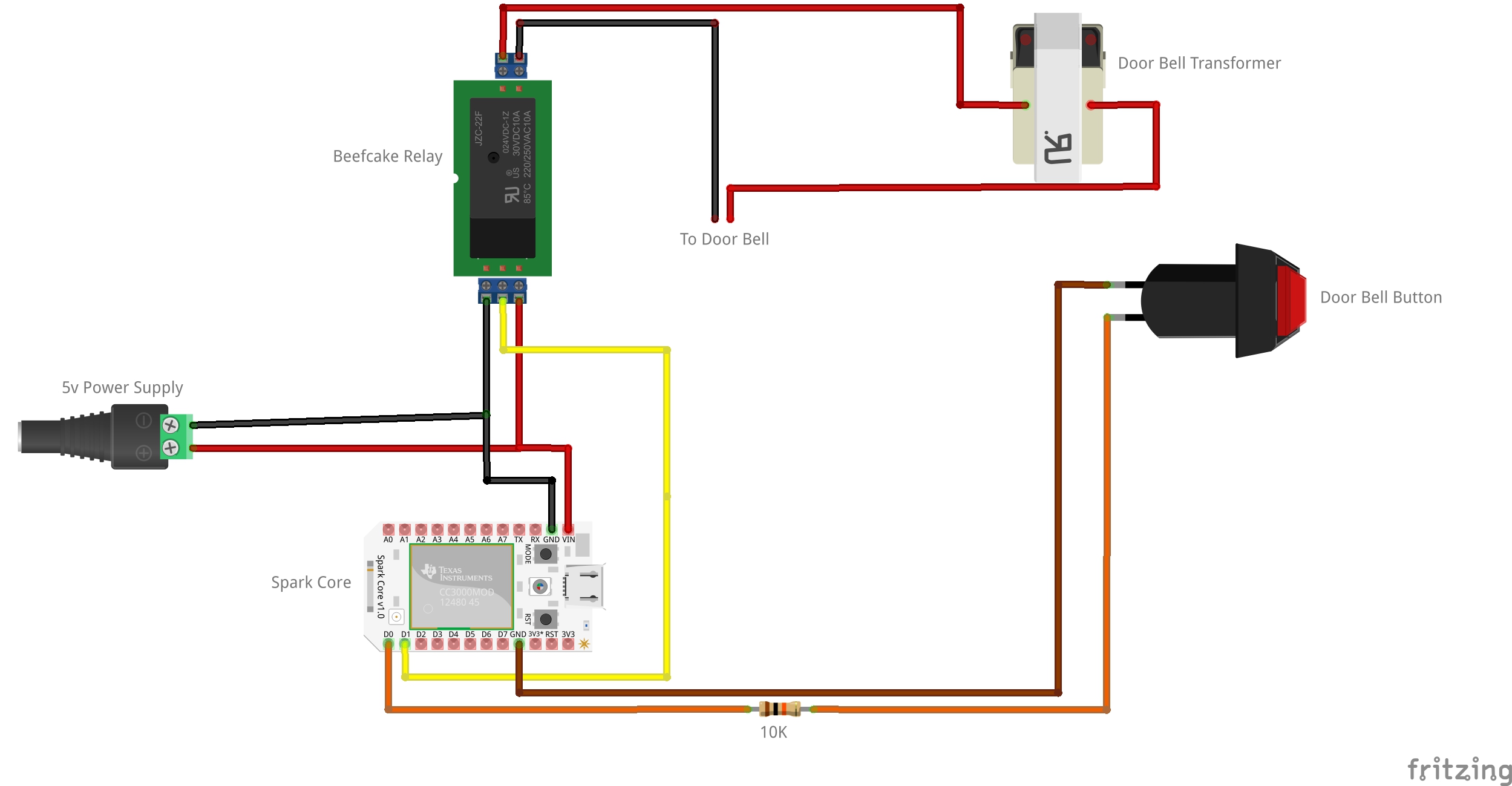
Wiring Diagram
I used Fritzing to draw this wiring diagram. I find these Fritzing diagrams more useful when you are starting out with electronics. They are easier to follow that schematics when you are just starting out (at least for me).
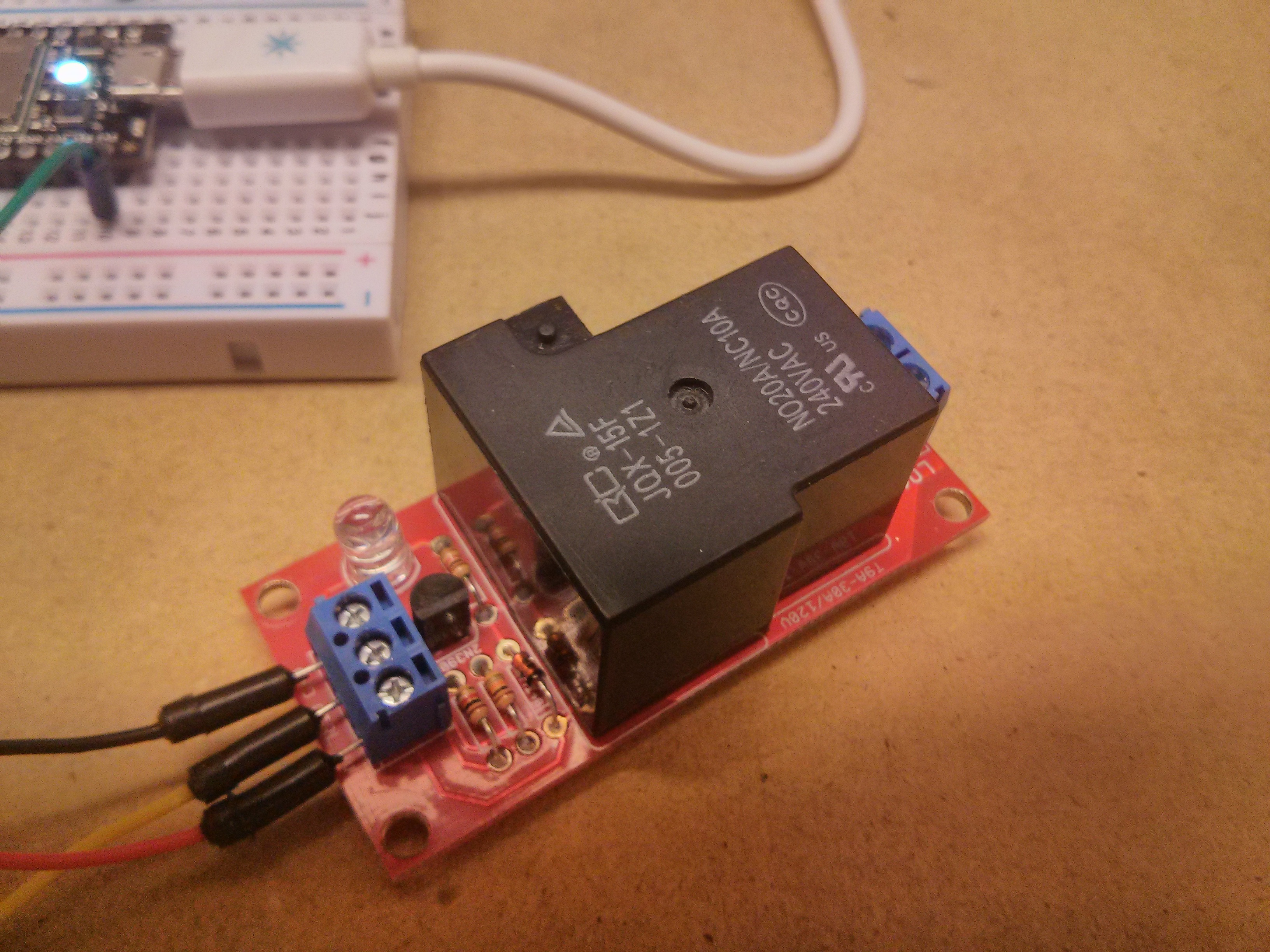
Relay
This is the Beefcake relay kit from Sparkfun. This is a fun and easy kit to solder up to sharpen your skills. It comes with all the necessary diodes and resistors and transistors to make the relay work properly. You could put all those things in yourself and add them to the protoboard, but I wanted the soldering practice without having to worry about more complicated wiring with this simple project. So I went with the Beefcake relay.
This particular relay requires 5v to power it, so the Spark Core's 3.3v will not have enough juice to power the relay. The Spark Core's 3.3v WILL however be enough to trigger the control line.
Spark Core (Now Particle Photon)
Because I couldn't say it any better, here is what Spark says about their own Spark Core:
The Spark Core is a complete Wi-Fi enabled development platform that allows users to create connected devices with ease. The Core is code-compatible with Arduino, which means you can use your existing Arduino code with the Core with little or no modifications.*
The Core has a built-in Wi-Fi module, a powerful 32-bit ARM microcontroller and 2MB of FLASH memory. You don't need any additional hardware to get started. The Spark Core offers Over-The-Air firmware updates via it's web based IDE, allowing the user to remotely write and transfer code to the Core, as well as a REST API provided through Spark’s free cloud service, the Spark Cloud. All you need is a web browser and an internet connection.
These little things are awesome, I see lots of projects in the future for these guys.
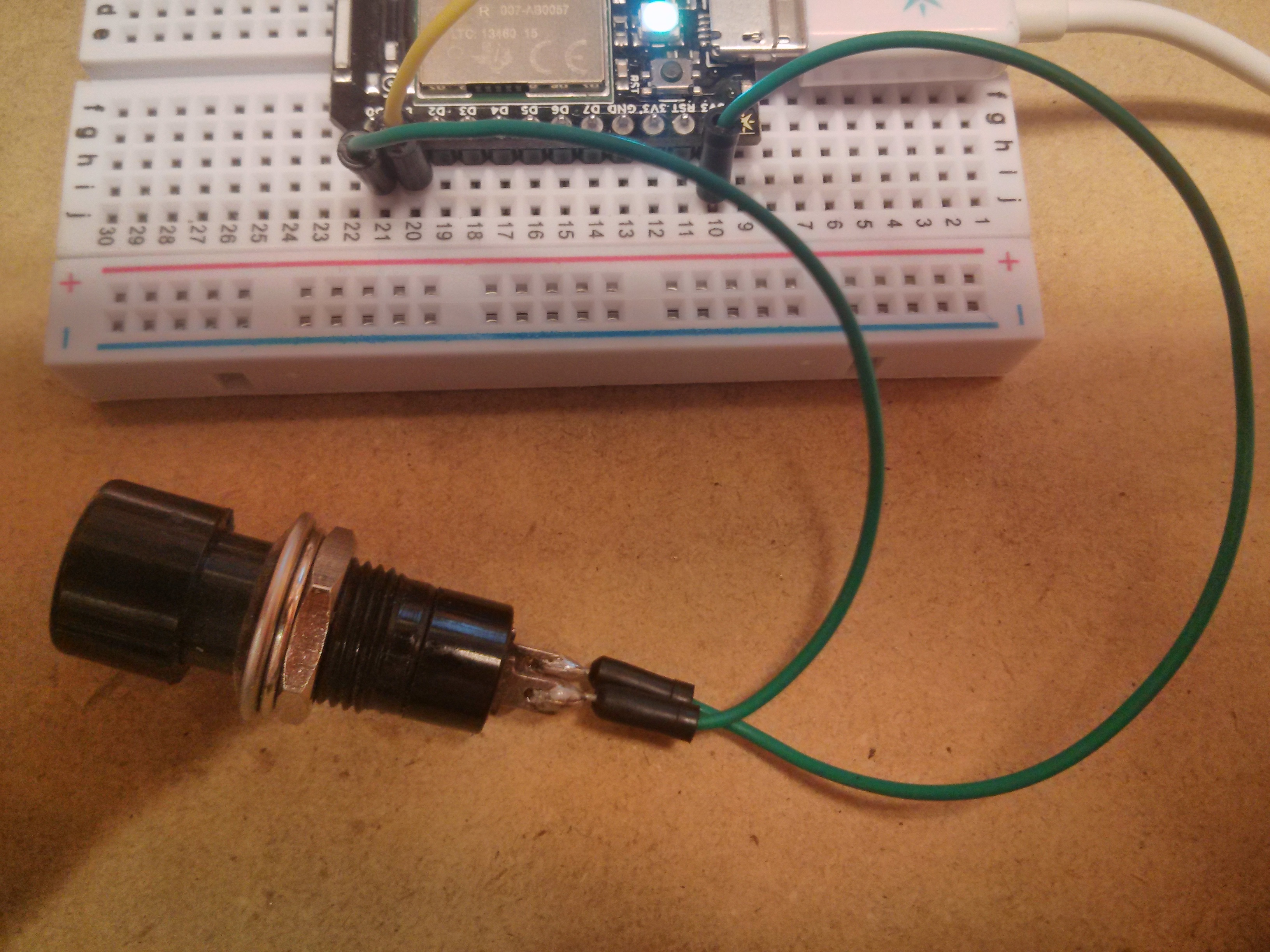
Code Name: TDRB
I needed a way to test the project on the workbench without having to get up and run outside each time to push the doorbell, so I decided to solder up a temporary doorbell replacement button, or TDRB. This saved me from having to make many trips to the front door while testing.
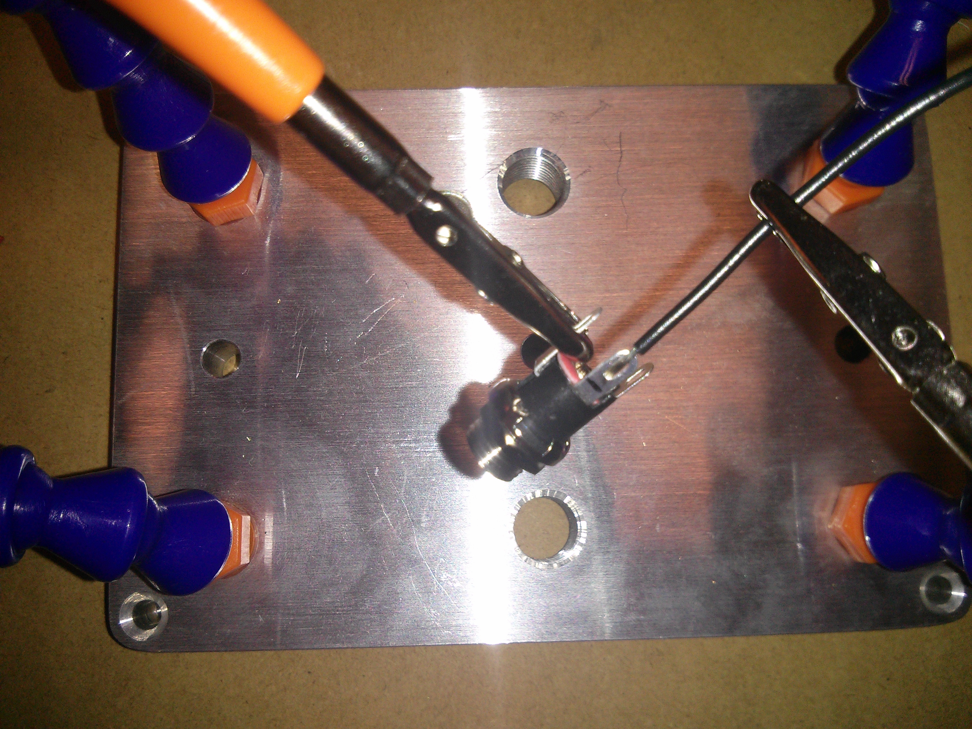
Soldering the Power Jack
Solder the wires to the power jack. Use a multimeter to make sure you are soldering to the correct terminals.
I got this nifty third hand from Sparkfun you should go pick one up for yourself. Very handy.
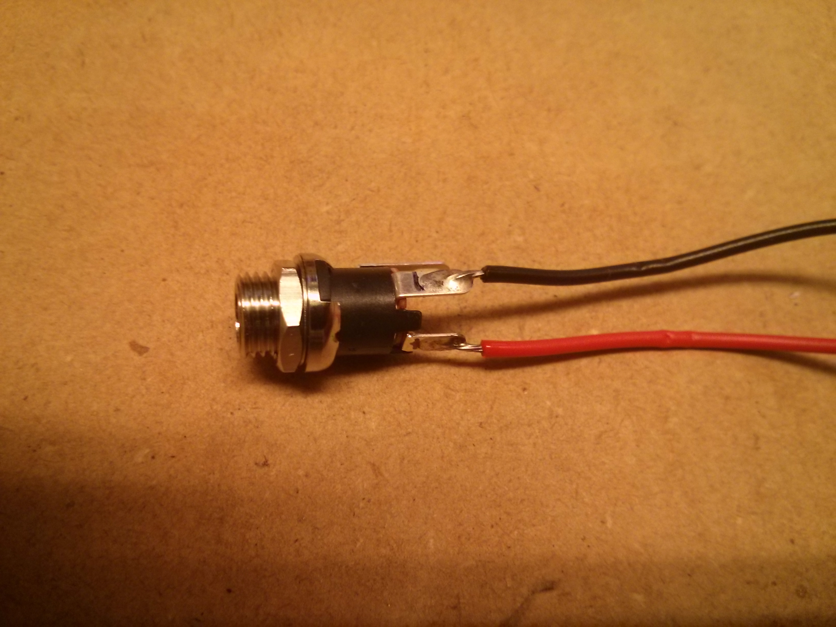
Soldered Power Jack
Power jack ready to go, as you can see, I marked the postive and negative terminals with a Sharpie so that I wouldn't get them mixed up when soldering. I would suggest you do the same. I would hate for you to blow up your project before it really starts.
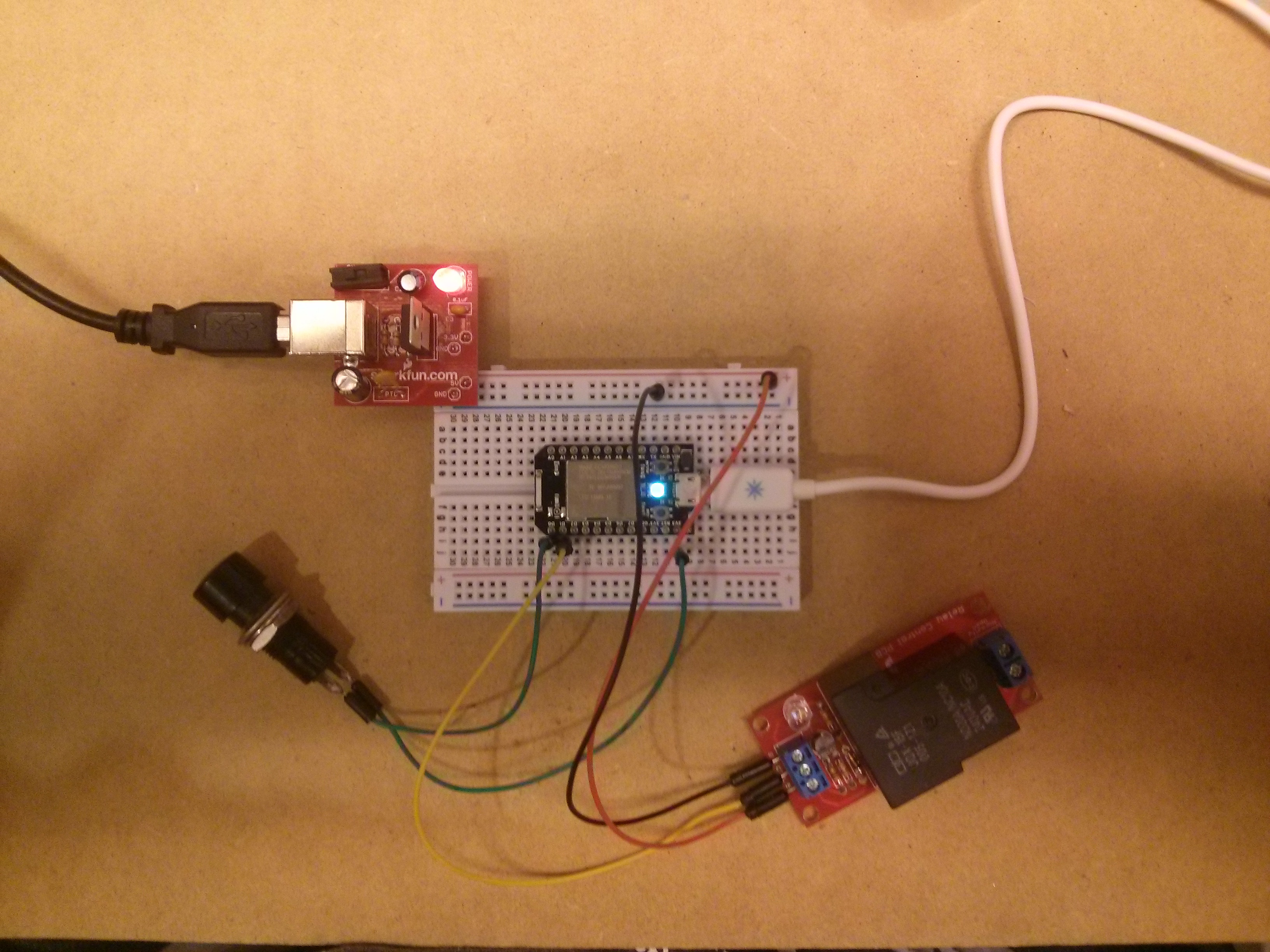
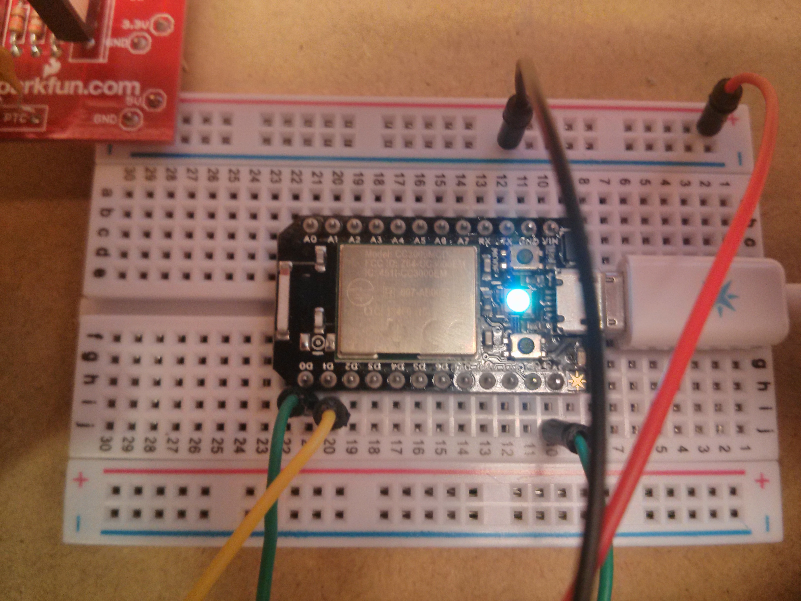
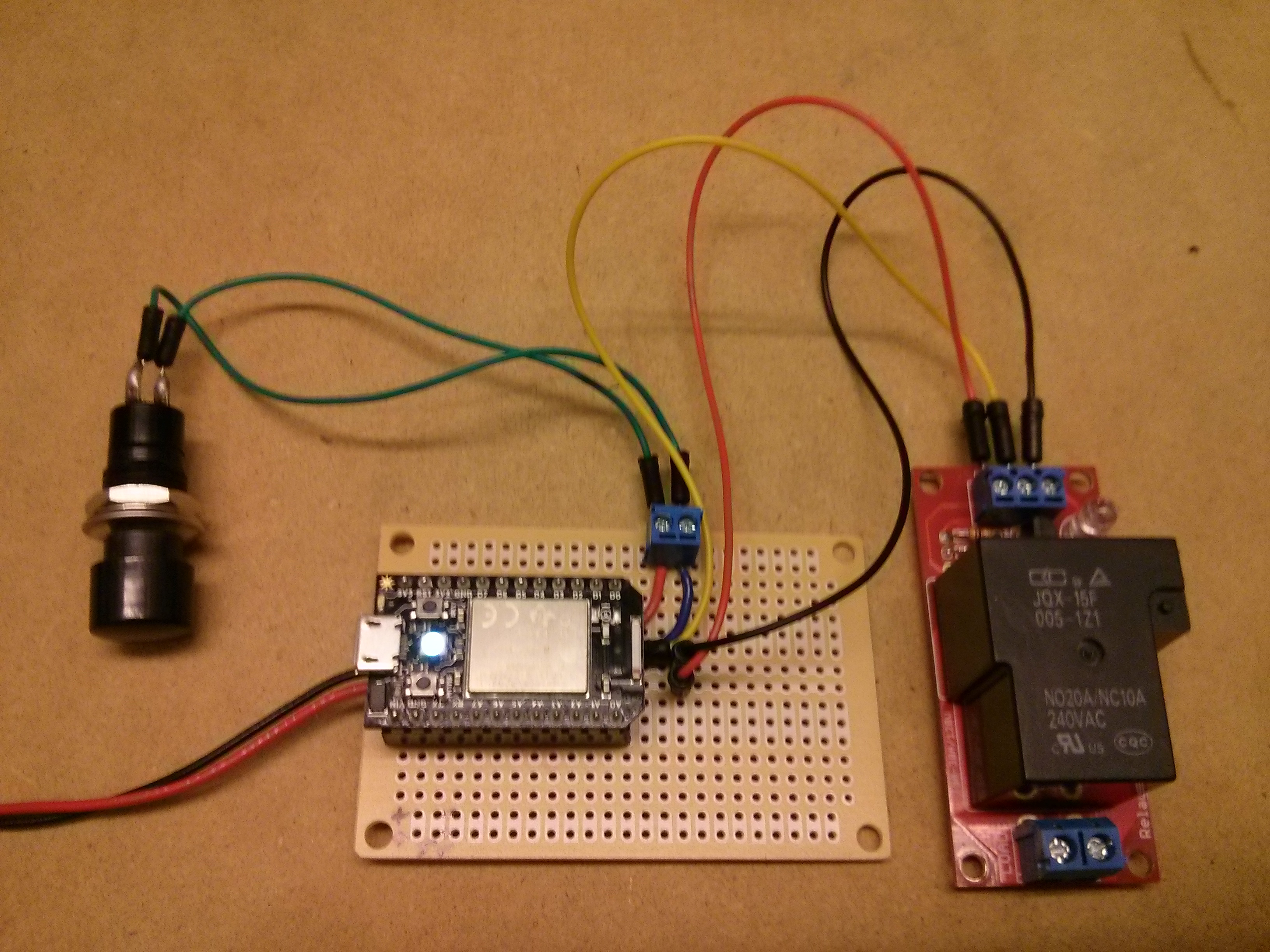
Breadboarding
Hook everything up on a breadboard before you start. This will ensure that you get everything hooked up correctly before soldering down on the protoboard.
1. Hook up one end of the switch to pin D0 on the Spark Core. Hook the other end of the switch to GND (Ground).
2. Hook up pin D1 to CTRL on the Beefcake Relay. Then hookup 5v on the relay to the positive rail on the breadboard and the GND to the negative rail on the breadboard.
3. Hook up from the positive rail to the VIN pin on the Spare Core. Remember, do not hook up a power supply larger than 6 volts to this pin. Also do not use this pin if you are powering the Spark with a USB cable. Next, hook up a wire from the GND pin to the negative rail of the breadboard.
4. Hook up the positive terminal from your 5 volt power supply to the positive rail on the breadboard then the negative terminal to the negative rail.
You should now have power to your Spark and relay. Connect the Spark Core to the Spark Cloud. For instructions on how to do this, check out Spark's documentation.
Edit the included code, or write your own, then upload it to the Spark Core. Test out the "doorbell" while it is sitting in front of you and work out any kinks that you might have before permanently soldering parts to the protoboard.
Installed on Protoboard
Begin by soldering the female headers onto the protoboard. The Spark Core has 12 pins on each side, so use two 6-pin female headers for each side. It is easier to keep the headers straight when soldering them if you push them onto the Spark first then solder them to the board. This will ensure that the Spark will fit into the female headers.
Now transfer each component from the breadboard to the protoboard and solder it in place and use the connected soldering pads on the bottom of the protoboard for connectivity. Instead of soldering on the TDRB, solder on the 2-pin screw terminal.
Something I figured out when I first installed the Smart Doorbell into my old fashioned doorbell system is that it would get set off by hooking up the doorbell's wires. So I fixed this by inserting a 10K resistor in between one of the screw terminals and pin D0 on the Spark. This took care of any interference.
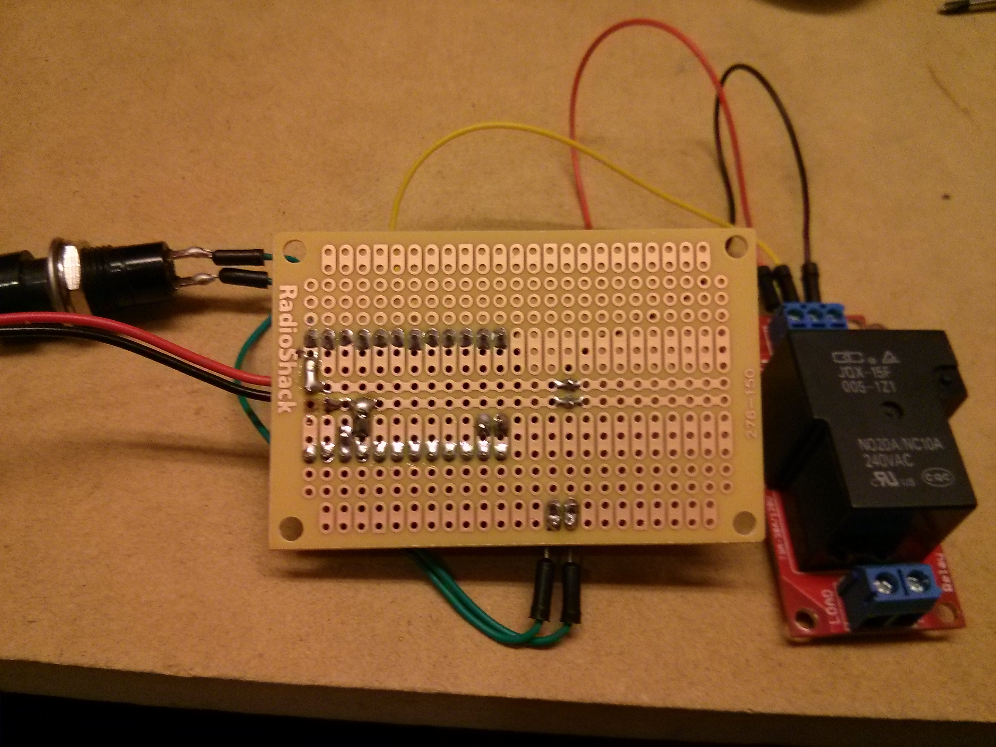
Back of Protoboard
This is how I soldered my protoboard. Be careful with the Radio Shack protoboards, if you leave the heat of the soldering iron on too long, you will burn off the soldering pads. Luckily where I burned off the pad I was able to move it over and try again. So keep the soldering time on each component to a minimum!
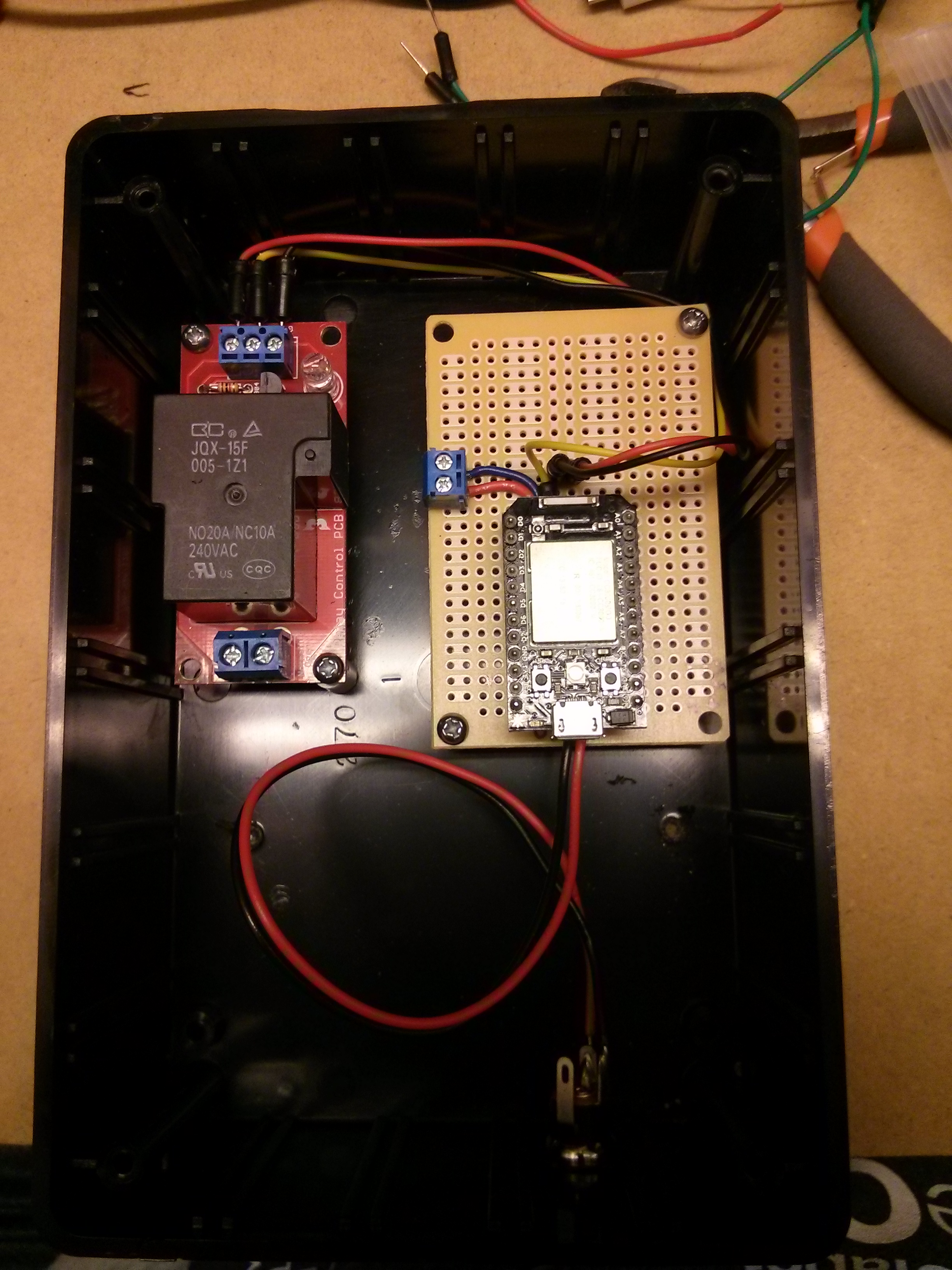
Installed in Project Case
Once you are done soldering everything to the protoboard, it is time to figure out how all of it will fit in the project box.
When you figure out how to lay it out you will need to drill a hole for the power jack and for the garage door wires to slip through.
Install the power jack and secure the protoboard and relay with at least one screw to keep everything stay in place.
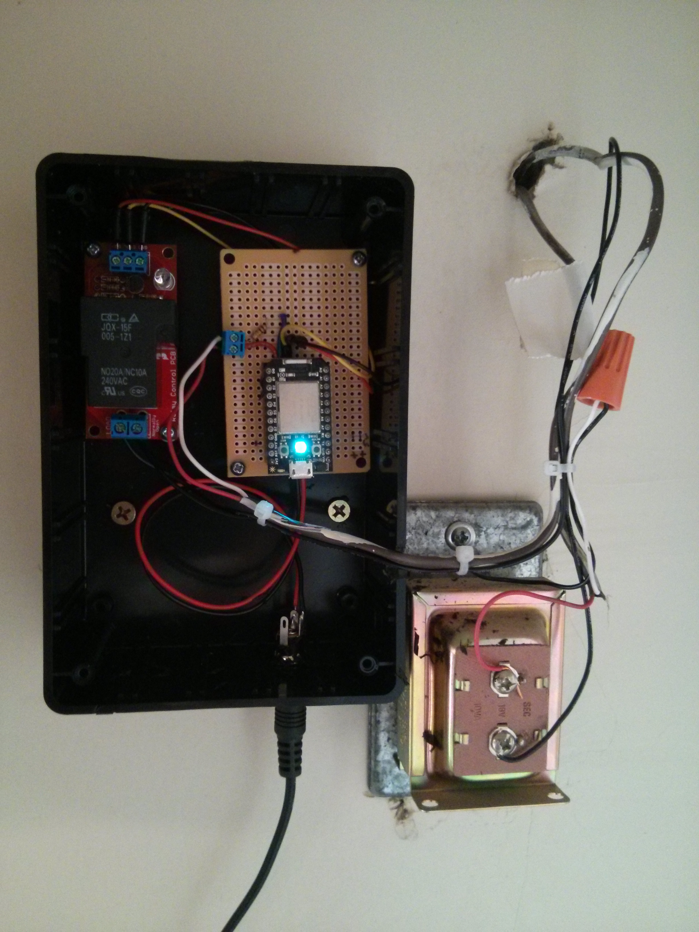
Mounted on Wall
I used two screws to screw the box into the sheetrock next to my doorbell transformer. When hooking up wires to your transformer, remember, this is A/C voltage you are working with. Be careful and don't hook A/C voltage directly to your project, you must use the relay!

Finished!
This is the doorbell with the cover on, ready for action. I hope you have had success in your build and you are as happy with yours as I am with mine.
Future Expansion
I have a few ideas for expanding this project in the future. The first idea is to be able to set up "quiet hours" for when you want the doorbell to text you, but not actually ring the doorbell. This would be great if you have a sleeping baby.
Another idea is to change out the old fashioned "Ding-Dong" doorbell for an mp3 shield and some speakers so you could play custom songs for your doorbell.
The options are limitless, if you have any great ideas to add to this project, I want to hear about them. Send them to me!